I added the audio transistors.
Before diving into this modification, I wanted to see how deteriorated the sound is when you try to link everything on the same power supply WITHOUT transistors. So I made this little video. You can hear the difference !
First, I noticed that my three little wires (on the output of the VS1053) were badly soldered and caused a short-circuit somewhere. So I removed them, and replaced them with a naked Jack plug. (I took it from a selfie stick. True story. These selfie sticks have an audio Jack plug to be able to take a shot from a button near the hand, that acts just like a button from headphones with mic. End of the story, back to business :p )
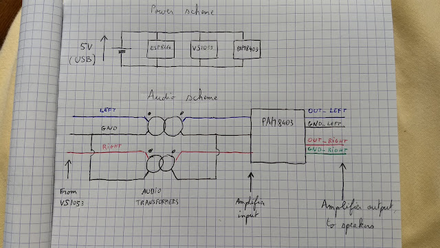
I wired the output of the VS1053 to the input of the transformers, and I wired the output of the transformers to the input of the PAM8403 (the amplifier). Since on the input and on the output, they have common ground between the two channels, I kept the common ground. You can see a rough scheme below (the "Audio scheme" on the bottom).
I also replaced the power source I soldered on the PAM8403 (the amplifier) by a nice socket.
Then, I wired with pluggable wires the power input of the PAM8403 with the one on the VS1053 (which is also the one on the ESP8266), so that the 3 components are powered in parallel by the same power input (the USB from the ESP8266 actually). That's the "Power scheme" on the top you can see below.
At first, I tried to put these audio transformers without any special care, and I placed them very close to each other. I noticed that there was a leakage of the left channel in the right channel, and the other way around too ! You could hear a little the left channel in the right speaker, and the right channel in the left speaker. I assumed that these transformers are not very well isolated and they leak their magnetic field into each other ! To avoid this magnetic field leakage, I placed them the farthest I could (like 6cm apart) and then I couldn't hear that audio leakage. Be careful of where you place your audio transformers !
Here's a little close-up :

Finally, putting it together, my speakers have quite a good punch !

Before diving into this modification, I wanted to see how deteriorated the sound is when you try to link everything on the same power supply WITHOUT transistors. So I made this little video. You can hear the difference !
First, I noticed that my three little wires (on the output of the VS1053) were badly soldered and caused a short-circuit somewhere. So I removed them, and replaced them with a naked Jack plug. (I took it from a selfie stick. True story. These selfie sticks have an audio Jack plug to be able to take a shot from a button near the hand, that acts just like a button from headphones with mic. End of the story, back to business :p )
I wired the output of the VS1053 to the input of the transformers, and I wired the output of the transformers to the input of the PAM8403 (the amplifier). Since on the input and on the output, they have common ground between the two channels, I kept the common ground. You can see a rough scheme below (the "Audio scheme" on the bottom).
I also replaced the power source I soldered on the PAM8403 (the amplifier) by a nice socket.
Then, I wired with pluggable wires the power input of the PAM8403 with the one on the VS1053 (which is also the one on the ESP8266), so that the 3 components are powered in parallel by the same power input (the USB from the ESP8266 actually). That's the "Power scheme" on the top you can see below.

At first, I tried to put these audio transformers without any special care, and I placed them very close to each other. I noticed that there was a leakage of the left channel in the right channel, and the other way around too ! You could hear a little the left channel in the right speaker, and the right channel in the left speaker. I assumed that these transformers are not very well isolated and they leak their magnetic field into each other ! To avoid this magnetic field leakage, I placed them the farthest I could (like 6cm apart) and then I couldn't hear that audio leakage. Be careful of where you place your audio transformers !
Here's a little close-up :

Finally, putting it together, my speakers have quite a good punch !

After that, I have to wait for my microcontrollers to arrive to develop my interface. I de-soldered some push-buttons from the original radio, and two rotary knobs. I'm pretty sure the rotary knobs are delivering some Grey code, I don't know if I will use them. I mean, isn't is simpler to use an old scroll wheel from a mouse ? Each time you roll, it's like a button is pressed. You get 2 buttons, one for rolling forward, one for rolling backward. I'll think of this.
In the future, I'll have to do some work to make a beautiful front face, with room for the screen and for some buttons. But I'm afraid that won't be anytime soon (my microcontrollers haven't left China yet :( )
See you !
Comments
Post a Comment